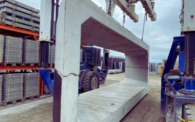
Precast Concrete Headwalls

Croom Concrete Headwalls can be quickly and easily installed by semi-skilled labourer and there are fewer joints which reduce the likelihood of infiltration.
Croom precast concrete headwalls for drainage outfall connections into open water areas including collection ponds, swales and rivers.
The strength and durability of precast concrete headwalls preserves the surrounding environment by minimising erosion at the outfall connection.
The quick positioning of precast concrete headwalls is a distinct advantage over ready mixed solutions with no on-site shuttering or formwork required. This proves ideal at difficult to reach areas and where time is limited.
Features:
- Low maintenance.
- Cost effectiveness.
- Quick fit installation.
- Design specific solution.
- Longevity.
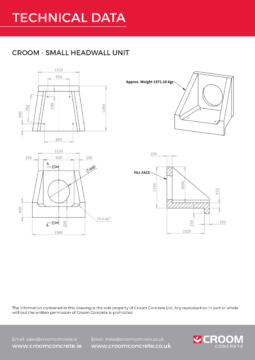
TECHNICAL DATA
Precast concrete headwalls can accommodate clay, concrete or plastic pipeline sizes, as follows:

* Hole size supplied in headwall will be wider than pipe Outer Diameter
The tables below contain details of the current stock of hole sizes available for each size headwall based on our stock of hole formers. We recommend hole sizes to be a minimum of 20mm wider than the pipe outer diameter.

If you require a size not listed call 061 397 479 or email info@croomconcrete.ie to see how we can help.
The aperture within the headwall will be sized and positioned to meet your requirements, so please contact us with your specific scheme details.
A range of accessories are available including flap valves, penstocks, safety grates (flat, hinged & cranked) and handrails. Ask us about relevant accessories to save time on site.
Lifting loops attached to cast in lifting sockets enable easy manoeuvring with standard chains.


INSTALLATION INSTRUCTIONS
SCOPE
Precast Concrete Headwalls are manufactured in the following sizes; small, medium, large and extra large and can be installed pre-fitted with a range of flap valves. Other accessories such as penstocks, grates and handrails are also available (fitted by others).
Table 1 below lists typical concrete pipe sizes compatible with our headwall range.
The hole will be sized to meet your requirements so please make sure you check the proposed hole size is compatible with your pipe’s outer diameter.
Croom precast concrete headwalls for drainage outfall connections into open water areas including collection ponds, swales and rivers.
The strength and durability of precast concrete headwalls preserves the surrounding environment by minimising erosion at the outfall connection.
The quick positioning of precast concrete headwalls is a distinct advantage over ready mixed solutions with no on-site shuttering or formwork required. This proves ideal at difficult to reach areas and where time is limited.
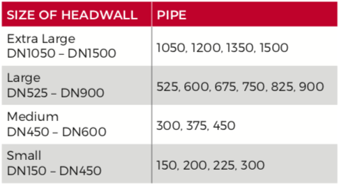
Table 1: Summary of Headwall Pipe Sizes
Features:
- Low maintenance.
- Cost effectiveness.
- Quick fit installation.
- Design specific solution.
- Longevity.
RECEIPT OF GOODS
On receipt, the delivery should be checked for the following:
- The delivery note corresponds to the goods on the consignment.
- Inspect headwalls for any sign of damage which could compromise performance.
- Headwalls are stamped with the production date.
HANDLING AND STORAGE
HANDLING
Unloading and handling on site must be undertaken with care to avoid damage to products.
Particular care must be taken to avoid damage to the toe end. Once off-loaded, headwalls should be placed evenly on timber beams.
Where possible, off-loading should occur at the location nearest to installation.
Small, Medium and Large Headwalls are to be off-loaded using 4No. lifting anchors cast into the units. Suitably checked and rated lifting loops will affix to cast in anchors; these will be used in conjunction with a suitably rated four-legged chainset to move and set the units in place.
The Extra Large Headwall is manufactured as a two piece unit. Each unit is to be off-loaded using 3No. lifting loops attached to a suitably rated three-legged chainset. The units will use these lifting anchors and corresponding lifting loops for off-loading, manoeuvring into position and to join both halves.
Under no circumstances should lifting loops be used to facilitate rotation of the units. If rotation is required, suitable rotating eyes must be used.

LIFTING POINTS DESIGN
The lifting points design has been carried out following the recommendations of the lifting systems suppliers. The calculation model is based on all the different situations the element is going to address during its life: from casting, demoulding, storage, transport loading, off-loading to final site installation.
The model starts using the weight of the element as the main parameter. Then it checks thedemoulding process considering the adhesion forces to the mould, the number of lifting points predefined, the angle of the chain used to handle the element (always less than 30 degrees against the vertical) and finally, in order to reduce the dynamic effects, it is recommended to use a lifting speed of less than 90 m/s. After that it is checked the handling process where it is considered a lifting speed that can be greater than 90 m/s. In both cases it is used a dynamic factor to take into account the dynamic effects.
The final lifting point design picks out the maximum value of the previous calculations. The selected value defines the minimum required load capacity of the anchor to be used. This parameter and other aspects such as concrete strength, distance to the edges, depth of the unit, etc., determine the commercial unit to be employed.
The following table shows a summary of the number of lifting points of every unit and the minimum leg-length of the chain to meet the 30 degrees rule.
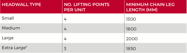
Extra large headwall is manufactured in two pieces. So the number of lifting point corresponds to one of the pieces.
STORAGE
Headwalls should be stored on firm, even ground with timber supports to avoid damage to the toe. Under no circumstances are units to be stacked.
INSTALLATION PROCEDURE
SMALL, MEDIUM & LARGE
Install and cut the final section of pipe that will meet the headwall.
Make sure the pipe is fully fitted, leaving the first (or end) section uncovered from backfill to install the headwall.
Excavate to the required formation level and place a mimimum 100mm thick bed of lean mix concrete (GEN1).
Check headwall hole diameter and outside diameter of pipe are compatible. Use the case in lifting anchors and associated lifting loops with a suitably rated four legged chainset.
Set the headwall onto the bedded surface, aligning the headwall to the centre of the hole. To ease positioning, use of a shim is recommended to ensure the correct central location.
Install the headwall onto the end of the pipe.
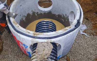
A hydrophilic sealant should be applied to the headwall opening and the end of the pipe section; this will ensure a tight seal. The pipe is to be sealed to the headwall opening by mortar, or similar, by others.
EXTRA LARGE
Stanton Bonna Extra Large Headwalls are constructed as a two-piece precast unit, which are then fixed together using an adhesive mortar on site.
Install and cut the last section of pipe that will meet the headwall.
Make sure the pipe is fully fitted, leaving the last section uncovered from backfill ready for installation.
Excavate to the required formation. Place and compact a minimum of 250mm of 50mm drainage stone and then cover with a minimum 100mm thick bed of lean mix concrete (GEN1).
Check headwall hole diameter and outside diameter of pipe are compatible. Use the cast in lifting anchors and associated lifting loops with a suitably-rated three-legged chainset to set the headwall onto the bedded surface.
Check the headwall hole is positioned correctly and will align with the cntre of the pipe. To ease positioning, use of a shim is recommended to ensure the correct central location.
Ensure the join is clean and free of debris, then lay a nominal 10mm bed of 2-part Thixotropic Epoxy adhesive (or similar) to the join.
Ensure equivalent join on second unit is clean and free of debris. Lift the unit into the correct position, making sure to remove excess adhesive.
A hydrophilic sealant should be applied to the headwall opening and the end of the pipe section; this will ensure a tight seal. The pipe is to be sealed to the end of the headwall by mortar or similar (by others).
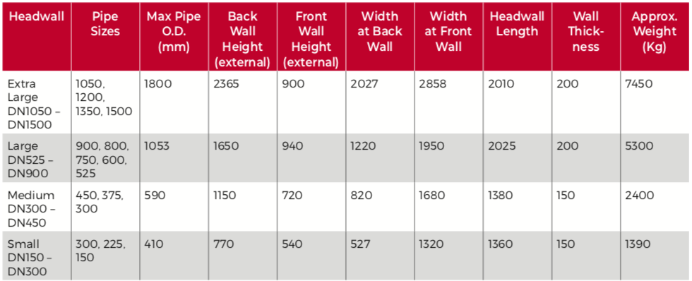
Table 2: Headwall Dimensions

Right to Change: The specifications given in this document are believed to be correct but are not guaranteed. Croom Concrete reserve the right to alter any specifications given in accordance with its policy of continuous product development. All rights reserved.


Would you like to know more about our civil products?
BLOG

⚙ Why Choose our Precast Concrete Wall Panels ❓
1️⃣ . Versatility: Our wall panels can be used in a wide range of applications, from residential homes and...
Trial erection day.
Trial erection day.⚙ Top class work from our team producing this bespoke 30t splayed box culvert. Always...

☑New 10 meter lift shaft
☑ New 10 meter lift shaft installed in Evergreen Business Park, Little island, Co. Cork.➡ Contractor:...

☑ Another project with Sorensen Civil Engineering Ltd
☑ Another project with Sorensen Civil Engineering Ltd being completed and delivered, this time we are on a...

Lift Shaft
🏗️Delighted to see our Lift Shaft being fitted at Blarney Business Park. 🤝Thank you Summerhill...
1200mm Precast Catchment Pits
☑ Great to see our 1200mm precast catchment pits getting installed on a current road project.🛑 We can cater...
Our Philosophy
''We are carrying out constant investment and innovation to be the industry leaders in an industry that is constantly improving. We are always ahead of our customers changing requirements.''
Croom Concrete
